2RS Series Steel on PTFE Maintenance-free
Brass lined with an antifriction film, consisting PTFE
Mating materials: Steel on PTFE Maintenance-free
Standard : 2RS Version, Special version 2RS sealing
Inner Ring : Antifriction bearing steel, hardened, ground and polished.
Bearing Shells : Brass lined with an antifriction film, consisting PTFE, cold formed around inner ring, outside diameter with thread, screwed into housing and secured with the rubber bellows.
Rubber Belows : Synthetic rubber with vulcanised brass slipring and steel locknut.
Housing : Sizes 8 to 12 free-cutting steel, sizes 14 to 30 tempering steel (standardi- sed), all sizes galvanised and chromatised.
Bushings : Tempering steel, hardened, bore and outside diameter ground, pressed into the inner ring. They are only used as intake of the brass abrasive rings of the rubber belows. Due to their low thickness they are not decicated to transmit radial and axial forces into the spherical bearing.
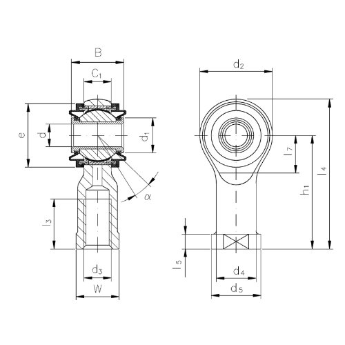
FEMALE
| Designation Right-hand |
Left-hand |
d | d3 | B | C1 |
| thread | thread | mm | |||
| Kl 8-D2RS | KIL 8-D2RS | M8 | 19 | 9,0 | |
| Kl 10-D2RS | KIL 10-D2RS | M10 | 21 | 10,5 | |
| Kl 12-D2RS | KIL 12-D2RS | M12 | 23 | 12,0 | |
| Kl 14-D2RS | KIL 14-D2RS | M14 | 26 | 13,5 | |
| Kl 16-D2RS | KIL 16-D2RS | M16 | 28 | 15,0 | |
| Kl 18-D2RS | KIL 18-D2RS | M18x1,5 | 30 | 16,5 | |
| Kl 20-D2RS | KIL 20-D2RS | M20x1,5 | 32 | 18,0 | |
| Kl 22-D2RS | KIL 22-D2RS | M22x1,5 | 35 | 20,0 | |
| Kl 25-D2RS | KIL 25-D2RS | M24x2 | 38 | 22,0 | |
| Kl 30-D2RS | KIL 30-D2RS | M30x2 | 44 | 25,0 |
(*) Deviates From Standard
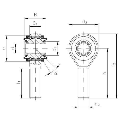
MALE
| Designation Right-hand |
Left-hand |
d | d3 | B | C1 |
| thread | thread | mm | |||
| KA 8-D2RS | KAL 8-D2RS | M8 | 19 | 9,0 | |
| KA 10-D2RS | KAL 10-D2RS | M10 | 21 | 10,5 | |
| KA 12-D2RS | KAL 12-D2RS | M12 | 23 | 12,0 | |
| KA 14-D2RS | KAL 14-D2RS | M14 | 26 | 13,5 | |
| KA 16-D2RS | KAL 16-D2RS | M16 | 28 | 15,0 | |
| KA 18-D2RS | KAL 18-D2RS | M18x1,5 | 30 | 16,5 | |
| KA 20-D2RS | KAL 20-D2RS | M20x1,5 | 32 | 18,0 | |
| KA 22-D2RS | KAL 22-D2RS | M22x1,5 | 35 | 20,0 | |
| KA 25-D2RS | KAL 25-D2RS | M24x2 | 38 | 22,0 | |
| KA 30-D2RS | KAL 30-D2RS | M30x2 | 44 | 25,0 |
(*) Deviates From Standard
Tolerances : Acc. to DIN ISO 12240-4, schedule K, except: d = H10, B = +- 0,3
Note : With these rod ends, it is important to ensure that the tilt angle specified in the table ist not exceeded, either while mounting or during operation, otherwise the rubber bellows may be damaged.
Special Versions : Available on request.
| d1 | d2 | d4 | d5 | e | h1 | l3 | l4 = |
W | Load ratings stat C0 |
Tilt angle | Weight |
max |
= |
min |
housing kN |
a° | kg |
||||||
| 10,5 | 25 | 12,5 | 16 | 20 | 36 | 12 | 48,5 | 14 | 12 | 9 | 0,066 |
| 13,0 | 29 | 15,0 | 19 | 24 | 43 | 15 | 57,5 | 17 | 15 | 9 | 0,118 |
| 15,5 | 33 | 17,5 | 22 | 28 | 50 | 18 | 66,5 | 19 | 23 | 9 | 0,162 |
| 17,0 | 37 | 20,0 | 25 | 30 | 57 | 21 | 75,5 | 22 | 24 | 10 | 0,235 |
| 19,5 | 43 | 22,0 | 27 | 34 | 64 | 24 | 85,5 | 22 | 34 | 10 | 0,285 |
| 22,0 | 47 | 25,0 | 31 | 37 | 71 | 27 | 94,5 | 27 | 39 | 10 | 0,385 |
| 24,5 | 51 | 27,5 | 34 | 40 | 77 | 30 | 102,5 | 30 | 42 | 10 | 0,500 |
| 26,0 | 55 | 30,0 | 37 | 44 | 84 | 33 | 111,5 | 32 | 54 | 10 | 0,615 |
| 29,5 | 61 | 33,5 | 42 | 50 | 94 | 36 | 124,5 | 36 | 60 | 10 | 0,800 |
| 35,0 | 71 | 40,0 | 50 | 58 | 110 | 45 | 145,5 | 41 | 82 | 12 | 1,210 |
- Not Available
| d1 | d2 | e | h | l1 | l2 = |
Load ratings stat C0 |
Tilt angle | Weight |
max |
= | min |
housing kN |
a° | kg |
|||
| 10,5 | 25 | 20 | 42 | 25 | 54,5 | 10 | 9 | 0,055 |
| 13,0 | 29 | 24 | 48 | 28 | 62,5 | 15 | 9 | 0,100 |
| 15,5 | 33 | 28 | 54 | 32 | 70,5 | 23 | 9 | 0,140 |
| 17,0 | 37 | 30 | 60 | 36 | 78,5 | 24 | 10 | 0,200 |
| 19,5 | 43 | 34 | 66 | 37 | 87,5 | 33 | 10 | 0,260 |
| 22,0 | 47 | 37 | 72 | 41 | 95,5 | 39 | 10 | 0,350 |
| 24,5 | 51 | 40 | 78 | 45 | 103,5 | 42 | 10 | 0,460 |
| 26,0 | 55 | 44 | 84 | 48 | 111,5 | 54 | 10 | 0,560 |
| 29,5 | 61 | 50 | 94 | 55 | 124,5 | 60 | 10 | 0,740 |
| 35,0 | 71 | 58 | 110 | 66 | 145,5 | 82 | 12 | 1,120 |
- Not Available
![]()
Welcome to LRS mechanic world!
- Emekyemez Mah.Tersane Cad. Fütühat Sok. No:36 34421 KARAKOY-ISTANBUL / TURKIYE
- info@lrsrulman.com
- +90 212 292 6021
- W/H : 08:00 - 18:00
© LRS Linear Rolling Systems All rights reserved