RS Series Steel on PTFE Maintenance-free
Sizes 8 to 12 free-cutting steel, sizes 14 to 30 tempering steel, all sizes galvanized and chromatised.
Mating materials : Steel on PTFE Maintenance-free
Standard : RS Special version RS sealing available on request
Inner ring : Antifriction bearing steel, hardened, ground and polished.
Outer ring : Steel lined with an antifriction film, consisting PTFE.
Rubber bellows : Synthetic rubber.
Housing : Sizes 8 to 12 free-cutting steel, sizes 14 to 30 tempering steel (standar- dised), all sizes galvanized and chromatised.
Tolerances : Acc. To DIN ISO 12240-4, schedule K, except: d = H8, B = +-0.3
Note : With these rod ends, it is important to ensure that the tilt angle speci- fied in the table is not exceeded, either while mounting or during opera- tion, otherwise the rubber bellows may be damaged. Replacement for previous 2RS-version. Available on request.
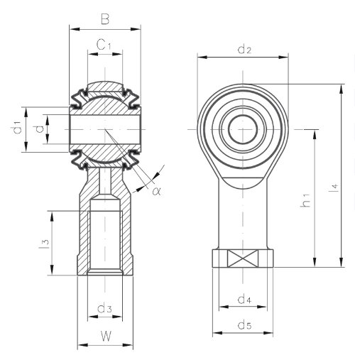
FEMALE
| Designation | d | d3 | B | C1 | d1 | |
| Righthand thread | Lefthand thread | mm | mm | mm | mm | mm |
| KI 8-DRS | KIL 8-DRS | 6 | M8 | 19 | 9.0 | 11.5 |
| KI 10-DRS | KIL 10-DRS | 8 | M10 | 21 | 10.5 | 13.5 |
| KI 12-DRS | KIL 12-DRS | 10 | M12 | 23 | 12.0 | 15.5 |
| KI 14-DRS | KIL 14-DRS | 12 | M14 | 26 | 13.5 | 17.5 |
| KI 16-DRS | KIL 16-DRS | 14 | M16 | 28 | 15.0 | 19.5 |
| KI 18-DRS | KIL 18-DRS | 16 | M18x1.5 | 30 | 16.5 | 22.0 |
| KI 20-DRS | KIL 20-DRS | 18 | M20x1.5 | 32 | 18.0 | 24.5 |
| KI 22-DRS | KIL 22-DRS | 20 | M22x1.5 | 35 | 20.0 | 26.5 |
| KI 25-DRS | KIL 25-DRS | 22 | M24x2 | 38 | 22.0 | 29.5 |
| KI 30-DRS | KIL 30-DRS | 25 | M30x2 | 44 | 25.0 | 35.0 |
(*) Deviates From Standard
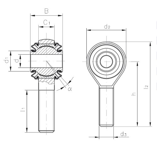
MALE
| Designation | d | d3 | B | C1 | d1 | |
| Righthand thread | Lefthand thread | mm | mm | mm | mm | mm |
| KA 8-DRS | KAL 8-DRS | 6 | M8 | 19 | 9.0 | 11.5 |
| KA 10-DRS | KAL 10-DRS | 8 | M10 | 21 | 10.5 | 13.5 |
| KA 12-DRS | KAL 12-DRS | 10 | M12 | 23 | 12.0 | 15.5 |
| KA 14-DRS | KAL 14-DRS | 12 | M14 | 26 | 13.5 | 17.5 |
| KA 16-DRS | KAL 16-DRS | 14 | M16 | 28 | 15.0 | 19.5 |
| KA 18-DRS | KAL 18-DRS | 16 | M18x1.5 | 30 | 16.5 | 22.0 |
| KA 20-DRS | KAL 20-DRS | 18 | M20x1.5 | 32 | 18.0 | 24.5 |
| KA 22-DRS | KAL 22-DRS | 20 | M22x1.5 | 35 | 20.0 | 26.5 |
| KA 25-DRS | KAL 25-DRS | 22 | M24x2 | 38 | 22.0 | 29.5 |
| KA 30-DRS | KAL 30-DRS | 25 | M30x2 | 44 | 25.0 | 35.0 |
(*) Deviates From Standard
Special versions : Available on request
| d2 max. | d4 | d5 | h1 | l3 min. | l4 = |
W | Load rating static C0 | Tilt angle | Weight |
| mm | mm | mm | mm | mm | mm | mm | kN | a° | kg |
| 25 | 12.5 | 16 | 36 | 12 | 48.5 | 14 | 12 | 9 | 0.066 |
| 29 | 15.0 | 19 | 43 | 15 | 57.5 | 17 | 15 | 9 | 0.118 |
| 33 | 17.5 | 22 | 50 | 18 | 66.5 | 19 | 23 | 9 | 0.162 |
| 37 | 20.0 | 25 | 57 | 21 | 75.5 | 22 | 24 | 10 | 0.235 |
| 43 | 22.0 | 27 | 64 | 24 | 85.5 | 22 | 34 | 10 | 0.285 |
| 47 | 25.0 | 31 | 71 | 27 | 94.5 | 27 | 39 | 10 | 0.385 |
| 51 | 27.5 | 34 | 77 | 30 | 102.5 | 30 | 42 | 10 | 0.500 |
| 55 | 30.0 | 37 | 84 | 33 | 111.5 | 32 | 54 | 10 | 0.615 |
| 61 | 33.5 | 42 | 94 | 36 | 124.5 | 36 | 60 | 10 | 0.800 |
| 71 | 40.0 | 50 | 110 | 45 | 145.5 | 41 | 82 | 12 | 1.210 |
- Not Available
| d2 max. | h | l1 min. | l2 = |
Load rating static C0 | Tilt angle | Weight |
| mm | mm | mm | mm | kN | a° | kg |
| 25 | 42 | 25 | 54.5 | 10 | 9 | 0.055 |
| 29 | 48 | 28 | 62.5 | 15 | 9 | 0.100 |
| 33 | 54 | 32 | 70.5 | 23 | 9 | 0.140 |
| 37 | 60 | 36 | 78.5 | 24 | 10 | 0.200 |
| 43 | 66 | 37 | 87.5 | 33 | 10 | 0.260 |
| 47 | 72 | 41 | 95.5 | 39 | 10 | 0.350 |
| 51 | 78 | 45 | 103.5 | 42 | 10 | 0.460 |
| 55 | 84 | 48 | 111.5 | 54 | 10 | 0.560 |
| 61 | 94 | 55 | 124.5 | 60 | 10 | 0.740 |
| 71 | 110 | 66 | 145.5 | 82 | 12 | 1.120 |
- Not Available
![]()
Welcome to LRS mechanic world!
- Emekyemez Mah.Tersane Cad. Fütühat Sok. No:36 34421 KARAKOY-ISTANBUL / TURKIYE
- info@lrsrulman.com
- +90 212 292 6021
- W/H : 08:00 - 18:00
© LRS Linear Rolling Systems All rights reserved